
Description
IES-PCI-403
Technical Specifications
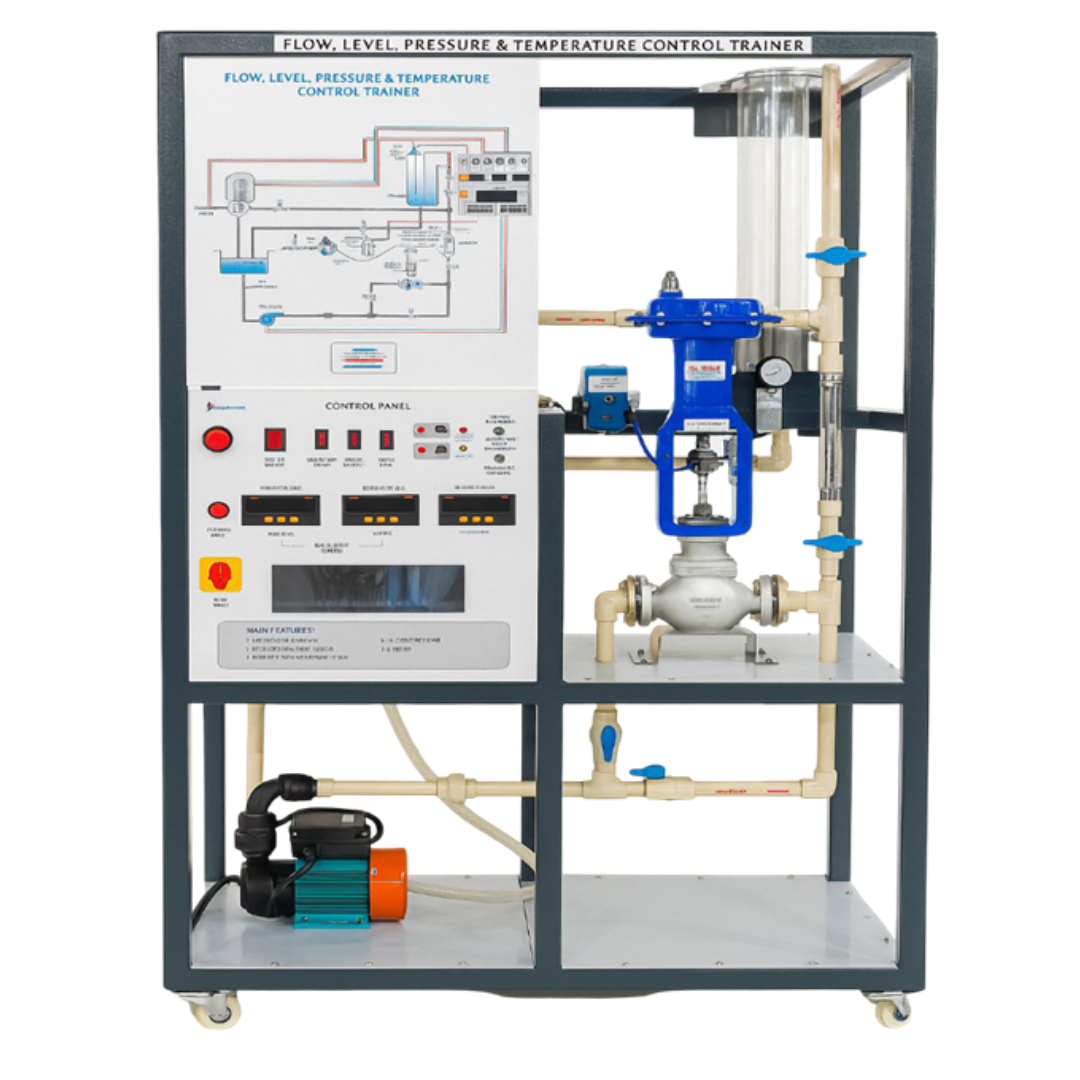
Flow Measurement System – Industrial flow transmitter / flow meter with measurement range 0–1000 LPH, providing 4–20 mA output signal and operating on 24 V DC supply for continuous flow monitoring.
Process Piping Network – Industrial ¾″ CPVC / ½″ stainless steel piping system equipped with ball valves and leak-proof fittings for realistic process flow experimentation.
Centrifugal Pump Unit – ½ HP centrifugal pump operating on single-phase 230 V AC supply, designed for continuous liquid circulation within the process system.
Process Reservoir (Sump Tank) – Storage tank constructed from stainless steel (1.5 mm) or polypropylene (5 mm) with 30-liter capacity for fluid storage and recirculation.
Electro-Pneumatic Conversion System – E/P converter capable of converting 4–20 mA electrical signal into pneumatic output of 3–15 psi for pneumatic valve actuation.
Air Supply System – Air compressor with 50 L tank capacity, discharge approximately 2 CFM, powered by 1–2 HP motor, operating on 230 V AC supply with working pressure 5–6 kg/cm².
Electrical Power Supply – Industrial SMPS power supply converting 230 V AC input to 24 V DC output (4.5 A) for powering transmitters and control instruments.
Air Preparation Unit – Filter–Regulator–Lubricator (AFR/FRL) assembly with pressure gauge and operating range 0–10 kg/cm² to ensure clean and regulated compressed air supply.
Flow Monitoring and Control Instruments – Rotameter flow indicator (100–1000 LPH range) combined with PID controller supporting universal / 4–20 mA input and 4–20 mA output, displaying Process Value (PV) and Set Point (SP) for closed-loop control.
Control Panel and Mechanical Structure – MS powder-coated electrical control panel with switches, indicators, DIN-rail terminals, organized cable tray wiring, and ½″ pneumatic control valve with equal percentage characteristic, mounted on a rigid MS floor-standing structure with heavy-duty caster wheels and locking brakes.
KEY FEATURES
Hands-on training for P, PI, PD and PID loop control with real-time observation
Manual & Auto tuning for controller dynamics understanding
External PLC/DCS integration capability
Safe, mobile design with MS powder-coated frame and caster wheels
Industrial-grade components for realistic training
Emphasis on industrial safety practices
RANGE OF EXPERIMENTS
ON–OFF flow control
Closed-loop flow control using P, PI, PD and PID modes
Manual vs auto tuning of PID controller
Open-loop and closed-loop response comparison
Transient response and stability analysis
Pneumatic control valve behavior in flow regulation
Integration with external PLC/DCS systems
GENERAL
Application: Flow Control Training for Process Control & Automation
Mounting: Floor-mounted mobile trainer
Safety: Proper earthing, regulated air supply, overflow protection, and electrical safety measures
Reviews
There are no reviews yet.